In this blogg post I will update with the status of my first Arduino project from the beginning to the final installation.
Goal:
In the garage, meassure the distance from the car from the wall and display the distance in m/cm on a LED Matrix RG display
Hardware:
1 * Ultrasonic Range Finder - Maxbotix LV-EZ0
4 * LED Matrix - Serial Interface - Red/Green
1 * Arduino Uno
The hardware has arrived from sparkfun.com and the first part goal was to get the Matrix display anything. I really struggeled with the start as there was a lot of code examples for the LED Matrix RGB display, but hardly any examples at all for the R/G version of it. After hours of try and failure I finally ended up with a code that could display something. Actually, my problem was not in the code but in the wiring from the Arduiono board to the LED Matrix. I will show later exactly how this shall be connected as there is not much detailed info available for this specific LED Matrix.
Wiring:
Arduino pin 10 => R/G matrix pin CS (chip select)
Arduino pin 11 => R/G matrix pin MOSI (data)
Arduino pin 13 => R/G matrix pin SCLK (serial clock)
Arduino pin 5v => R/G matrix pin VCC (power)
Arduino pin GND => R/G matrix pin GND (ground)
(I did a mistake and connected the matrix on MISO instead of MOSI).
OK, that was the wiring. Next I did a lot of testing with the code to be able to display a solid character on each of the 4 displays. When daisychain multiple LED matrix display with a backpack and you write to them through the serial port, they will automatically shift the letters as a rolling text over the 4 displays. The code I used to stop them is shown below. In this code I tend to replace the counter that stop the text with the actual code for reading the sonar sensor. That will now be my next test:
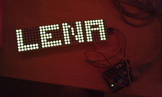
For now the code looks like this which display the name "LENA" on the 4 displays:
The counter "count" will later be replaced with reading from the Ultrasonic range finder to check if the distance has changed since last reading.
The code will be updated as the project moves forward.....
// Simple program to test using the Arduino with the RGB Matrix
// & Backpack from Sparkfun. Code is a combination of Heather Dewey-Hagborg,
// Arduino Forum user: Little-Scale, and // Daniel Hirschmann. Enjoy!
//
// The Backpack requires 125Khz SPI, which is the slowest rate
// at which the Arduino's hardware SPI bus can communicate at.
//
// We need to send SPI to the backpack in the following steps:
// 1) Activate ChipSelect;
// 2) Wait 500microseconds;
// 3) Transfer 64bytes @ 125KHz (1 byte for each RGB LED in the matrix);
// 4) De-activate ChipSelect;
// 5) Wait 500microseconds
// Repeat however often you like!
#define CHIPSELECT1 10//ss
#define CHIPSELECT2 10//ss
#define CHIPSELECT3 10//ss
#define CHIPSELECT4 10//ss
#define SPICLOCK 13//sck
#define DATAOUT 11//MOSI / DI
#define DATAIN 12//MISO / DO
int dataL[] =
{1,1,0,0,0,0,0,0,
1,1,0,0,0,0,0,0,
1,1,0,0,0,0,0,0,
1,1,0,0,0,0,0,0,
1,1,0,0,0,0,0,0,
1,1,0,0,0,0,0,0,
1,1,1,1,1,1,1,0,
1,1,1,1,1,1,1,0
};
int dataE[] =
{1,1,1,1,1,1,1,0,
1,1,1,1,1,1,1,0,
1,1,0,0,0,0,0,0,
1,1,1,1,0,0,0,0,
1,1,1,1,0,0,0,0,
1,1,0,0,0,0,0,0,
1,1,1,1,1,1,1,0,
1,1,1,1,1,1,1,0
};
int dataN[] =
{1,1,0,0,0,1,1,0,
1,1,1,0,0,1,1,0,
1,1,0,1,0,1,1,0,
1,1,0,1,0,1,1,0,
1,1,0,1,0,1,1,0,
1,1,0,0,1,1,1,0,
1,1,0,0,1,1,1,0,
1,1,0,0,0,1,1,0
};
int dataA[] =
{1,1,1,1,1,1,1,0,
1,1,1,1,1,1,1,0,
1,1,0,0,0,1,1,0,
1,1,1,1,1,1,1,0,
1,1,0,0,0,1,1,0,
1,1,0,0,0,1,1,0,
1,1,0,0,0,1,1,0,
1,1,0,0,0,1,1,0
};
char spi_transfer(volatile char data)
{
SPDR = data; // Start the transmission
while (!(SPSR & (1<<SPIF))) // Wait the end of the transmission
{
};
}
void setup()
{
byte clr;
pinMode(DATAOUT,OUTPUT);
pinMode(SPICLOCK,OUTPUT);
pinMode(CHIPSELECT1,OUTPUT);
digitalWrite(CHIPSELECT1,HIGH); //disable device 1
SPCR = B01010011; //SPI Registers
SPSR = SPSR & B11111110; //make sure the speed is 125KHz
/*
SPCR bits:
7: SPIEE - enables SPI interrupt when high
6: SPE - enable SPI bus when high
5: DORD - LSB first when high, MSB first when low
4: MSTR - arduino is in master mode when high, slave when low
3: CPOL - data clock idle when high if 1, idle when low if 0
2: CPHA - data on falling edge of clock when high, rising edge when low
1: SPR1 - set speed of SPI bus
0: SPR0 - set speed of SPI bus (00 is fastest @ 4MHz, 11 is slowest @ 250KHz)
*/
clr=SPSR;
clr=SPDR;
delay(10);
digitalWrite(CHIPSELECT1,LOW); // enable the ChipSelect on the backpack 1
delayMicroseconds(500);
spi_transfer('%');
spi_transfer(4); //configure SPI for 4 displays
delayMicroseconds(100);
digitalWrite(CHIPSELECT2,HIGH); //disable device 2
delayMicroseconds(500);
digitalWrite(CHIPSELECT3,HIGH); //disable device 3
delayMicroseconds(500);
digitalWrite(CHIPSELECT4,HIGH); //disable device 4
delayMicroseconds(500);
}
int count = 0; //counter used to make sure we clock in text only once
void loop()
{
if (count < 1) //check if we have run the loop once
{
// Display 1
delay(1000);
int index = 0;
digitalWrite(CHIPSELECT1,LOW); // enable the ChipSelect on the backpack
delayMicroseconds(500);
for (int i=0;i<8;i++) for (int j=0;j<8;j++)
{
spi_transfer(dataL[index]);
index++;
}
digitalWrite(CHIPSELECT1,HIGH); // disable the ChipSelect on the backpack
delayMicroseconds(500);
// Display 2
index = 0;
digitalWrite(CHIPSELECT2,LOW); // enable the ChipSelect on the backpack
delayMicroseconds(500);
for (int i=0;i<8;i++) for (int j=0;j<8;j++)
{
spi_transfer(dataE[index]);
index++;
}
digitalWrite(CHIPSELECT2,HIGH); // disable the ChipSelect on the backpack
delayMicroseconds(500);
// Display 3
index = 0;
digitalWrite(CHIPSELECT3,LOW); // enable the ChipSelect on the backpack
delayMicroseconds(500);
for (int i=0;i<8;i++) for (int j=0;j<8;j++)
{
spi_transfer(dataN[index]);
index++;
}
digitalWrite(CHIPSELECT3,HIGH); // disable the ChipSelect on the backpack
delayMicroseconds(500);
// Display 4
index = 0;
digitalWrite(CHIPSELECT4,LOW); // enable the ChipSelect on the backpack
delayMicroseconds(500);
for (int i=0;i<8;i++) for (int j=0;j<8;j++)
{
spi_transfer(dataA[index]);
index++;
}
digitalWrite(CHIPSELECT4,HIGH); // disable the ChipSelect on the backpack
delayMicroseconds(500);
count = count + 1; //update counter
}
}

Ingen kommentarer:
Legg inn en kommentar