onsdag 24. august 2011

How to configure IP-Symcon to support Eaton XComfort

In this blog post I will explain how to use the Home Automation software IP-Symcon to control light dimmers, switches, etc from Eaton XComfort. Since all documentation from IP-Symcon is on German, I had to do quite a lot try and failure before I got it all working. This post will explain in detail how you do this setup including all the details.

The first thing you need to do is of cause get a IP-Symcon license. This can be purchased directly from IP-Symcon and it takes just a couple of minutes to complete. Go to their web shop at http://www.ip-symcon.de/shop/software. I have purchased the Pro version as this give a whole lot of benefits.

Once you got the license, then you can download and install the software. The software is in English so the installation is straight forward with all default values.

Now, to control a Eaton XComfort system you will need to have some connection information from the XConfort system and you will need a device (CKOZ-00/03 see below) to send the RF signals from the machine running the IP-Symcon software that control the dimmers and switches +++. Now, this part might cost you or if you are lucky you may borrow some equipment from your local XComfort dealer. The equipment you need is:

1) Eaton XComfort USB Communication Interface - CKOZ-00/03
2) Eaton XComfort RS-232 Communication Interface - CRSZ-00/01

The USB interface is used for sending RF control signals to the XComfort actuators (dimmers, switches, etc), so this you will need to buy. The RS-232 interface cost about twice the USB intrerface and is only needed for a short period to program the actuators and create a connection between the actuators and the USB interface (you might be able to borrow or rent this interface from a local vendor). Tip: Both interfaces can be bought for a "low" cost from Poland (http://xcomfort-sklep.pl/content/1-delivery).

You should now connect the USB interface to you machine running IP-Symcon so it has power through the USB port and the green light is illuminated. You may want to upgrade the firmware, this is done using the "Eaton CI Update" software. Tip: You MUST update the firmware on a 32-bit Windows operating system as the device driver needed for the software does not work on a 64-bit system.

Download and install the "Eaton RF System" from their web site (do a Google search to find the latest version. I used 2.00 Norwegian version). Connect the RS-232 interface to your computer and start the Eaton RF System software. The user manual for this software is pretty good, so I will not explain in detail how you use it, but your goal is to scan for all your existing actuators, including remote controls and especially the USB interface CKOZ-00/03. You should now see all existing connection between the actuators, remote controls and switches. You should also see that the USB interface was discovered. Next, you need to draw a line between all the actuators and the USB interface. You should now have something that look like this:

Tip: Give all the actuators a descriptive name!

After all connections are finished, then right click and select "Create Data Point List". This is a text file which contains information about all the actuators and their connections and how they are controlled. We will use this file later to import the configuration into IP-Symcon.

Start the IP-Symcon Management Console and connect to your IP-Symcon server. The first step will be to import the XComfort configuration. You do this my selecting "Manage Configurations" and then press the "New" button. Select XComfort Configurator and click through the rest of the wizard. The configuration screen will now show. Click on the "Upload Data Point List" and browse to the file you saved earlier from the Eaton RF System program. Now all the configuration is imported into IP-Symcon.

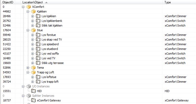
I would recommend that you organize the actuators and this is done by selecting "Logical TreeView" from the IP-Symcon Welcome page. I created the following structure (see picture below).

Once the structure is on plave, you can now move on to configure the IP-Symcon WEB interface. This is done by clicking on the "Configure WebFront" from the Welcome screen. Click New and go through the wizard. Once the WebFront configuration page is shown you can various web elements/part. The web part used to display your XComfort devices are the "Category" item. This item can be linked into a TabPane. The Category item is configured by pointing the "root" property to the root of the structure that you created earlier. See picture below.


My WebFront config looks like this:

And the result by browsing to http://<ip-symcon server>:82/

Tip: Create scripts that configure different themes. E.g "Evening", "Night", "Dinner", etc. A script can look like this:
<?
 //Start writing your scripts between the brackets
MXC_DimSet(59940 /*[Stue\Lys forstue ]*/, 30);
MXC_DimSet(28496 /*[Kjøkken\Lys kjøkken ]*/, 50);
MXC_SwitchMode(28025 /*[Stue\Lys skap ved TV ]*/, true);
MXC_DimSet(51422 /*[Stue\Lys spisebord ]*/, 50);
MXC_DimSet(22250 /*[Stue\Lys stuebord ]*/, 60);
MXC_SwitchMode(20792 /*[Kjøkken\Lys kjøkkenbenk ]*/, false);
MXC_SwitchMode(39724 /*[Trapp og Loft\Lys trapp loft ]*/, false);
MXC_SwitchMode(43107 /*[Stue\Lys ved soffa ]*/, false);
MXC_SwitchMode(16480 /*[Stue\Lys ved TV ]*/, false);
MXC_SwitchMode(52496 /*[Kjøkken\Stikk tak kjøkken ]*/, false);
MXC_SwitchMode(19669 /*[Stue\Stikk utg terrasse ]*/, false);
?>

Place the script in the logical structure and link them to the webconfig in the same way that you linked the actuators. See example below:
You can now by a single click set all actuators to a pre-defined configuration. Nice! :-)


fredag 19. august 2011

The beginning of the Arduino range sensor

In this blogg post I will update with the status of my first Arduino project from the beginning to the final installation.

Goal:
In the garage, meassure the distance from the car from the wall and display the distance in m/cm on a LED Matrix RG display

Hardware:
1 * Ultrasonic Range Finder - Maxbotix LV-EZ0
4 * LED Matrix - Serial Interface - Red/Green
1 * Arduino Uno

The hardware has arrived from sparkfun.com and the first part goal was to get the Matrix display anything. I really struggeled with the start as there was a lot of code examples for the LED Matrix RGB display, but hardly any examples at all for the R/G version of it. After hours of try and failure I finally ended up with a code that could display something. Actually, my problem was not in the code but in the wiring from the Arduiono board to the LED Matrix. I will show later exactly how this shall be connected as there is not much detailed info available for this specific LED Matrix.

Wiring:
Arduino pin 10 => R/G matrix pin CS (chip select)
Arduino pin 11 => R/G matrix pin MOSI (data)
Arduino pin 13 => R/G matrix pin SCLK (serial clock)
Arduino pin 5v => R/G matrix pin VCC (power)
Arduino pin GND => R/G matrix pin GND (ground)

(I did a mistake and connected the matrix on MISO instead of MOSI).

OK, that was the wiring. Next I did a lot of testing with the code to be able to display a solid character on each of the 4 displays. When daisychain multiple LED matrix display with a backpack and you write to them through the serial port, they will automatically shift the letters as a rolling text over the 4 displays. The code I used to stop them is shown below. In this code I tend to replace the counter that stop the text with the actual code for reading the sonar sensor. That will now be my next test:

For now the code looks like this which display the name "LENA" on the 4 displays:
The counter "count" will later be replaced with reading from the Ultrasonic range finder to check if the distance has changed since last reading.

The code will be updated as the project moves forward.....

// Simple program to test using the Arduino with the RGB Matrix
// & Backpack from Sparkfun. Code is a combination of Heather Dewey-Hagborg,
// Arduino Forum user: Little-Scale, and // Daniel Hirschmann. Enjoy!
//
// The Backpack requires 125Khz SPI, which is the slowest rate
// at which the Arduino's hardware SPI bus can communicate at.
//
// We need to send SPI to the backpack in the following steps:
// 1) Activate ChipSelect;
// 2) Wait 500microseconds;
// 3) Transfer 64bytes @ 125KHz (1 byte for each RGB LED in the matrix);
// 4) De-activate ChipSelect;
// 5) Wait 500microseconds
// Repeat however often you like!


#define CHIPSELECT1 10//ss
#define CHIPSELECT2 10//ss
#define CHIPSELECT3 10//ss
#define CHIPSELECT4 10//ss
#define SPICLOCK  13//sck
#define DATAOUT 11//MOSI / DI
#define DATAIN 12//MISO / DO

int dataL[] =
{1,1,0,0,0,0,0,0,
1,1,0,0,0,0,0,0,
1,1,0,0,0,0,0,0,
1,1,0,0,0,0,0,0,
1,1,0,0,0,0,0,0,
1,1,0,0,0,0,0,0,
1,1,1,1,1,1,1,0,
1,1,1,1,1,1,1,0
};

int dataE[] =
{1,1,1,1,1,1,1,0,
1,1,1,1,1,1,1,0,
1,1,0,0,0,0,0,0,
1,1,1,1,0,0,0,0,
1,1,1,1,0,0,0,0,
1,1,0,0,0,0,0,0,
1,1,1,1,1,1,1,0,
1,1,1,1,1,1,1,0
};

int dataN[] =
{1,1,0,0,0,1,1,0,
1,1,1,0,0,1,1,0,
1,1,0,1,0,1,1,0,
1,1,0,1,0,1,1,0,
1,1,0,1,0,1,1,0,
1,1,0,0,1,1,1,0,
1,1,0,0,1,1,1,0,
1,1,0,0,0,1,1,0
};


int dataA[] =
{1,1,1,1,1,1,1,0,
1,1,1,1,1,1,1,0,
1,1,0,0,0,1,1,0,
1,1,1,1,1,1,1,0,
1,1,0,0,0,1,1,0,
1,1,0,0,0,1,1,0,
1,1,0,0,0,1,1,0,
1,1,0,0,0,1,1,0
};

char spi_transfer(volatile char data)
{
SPDR = data;                    // Start the transmission
while (!(SPSR & (1<<SPIF)))     // Wait the end of the transmission
{
};
}

void setup()
{
byte clr;
pinMode(DATAOUT,OUTPUT);
pinMode(SPICLOCK,OUTPUT);
pinMode(CHIPSELECT1,OUTPUT);

digitalWrite(CHIPSELECT1,HIGH); //disable device 1

SPCR = B01010011;             //SPI Registers
SPSR = SPSR & B11111110;      //make sure the speed is 125KHz

/*
SPCR bits:
 7: SPIEE - enables SPI interrupt when high
 6: SPE - enable SPI bus when high
 5: DORD - LSB first when high, MSB first when low
 4: MSTR - arduino is in master mode when high, slave when low
 3: CPOL - data clock idle when high if 1, idle when low if 0
 2: CPHA - data on falling edge of clock when high, rising edge when low
 1: SPR1 - set speed of SPI bus
 0: SPR0 - set speed of SPI bus (00 is fastest @ 4MHz, 11 is slowest @ 250KHz)
 */

clr=SPSR;
clr=SPDR;
delay(10);


digitalWrite(CHIPSELECT1,LOW); // enable the ChipSelect on the backpack 1
delayMicroseconds(500);
spi_transfer('%');
spi_transfer(4);              //configure SPI for 4 displays
delayMicroseconds(100);
digitalWrite(CHIPSELECT2,HIGH); //disable device 2
delayMicroseconds(500);
digitalWrite(CHIPSELECT3,HIGH); //disable device 3
delayMicroseconds(500);
digitalWrite(CHIPSELECT4,HIGH); //disable device 4
delayMicroseconds(500);
}


int count = 0; //counter used to make sure we clock in text only once
void loop()           
{

  if (count < 1) //check if we have run the loop once
  {
  // Display 1
  delay(1000);
  int index = 0;                 
  digitalWrite(CHIPSELECT1,LOW); // enable the ChipSelect on the backpack
  delayMicroseconds(500);
  for (int i=0;i<8;i++) for (int j=0;j<8;j++)
  {
    spi_transfer(dataL[index]);
      index++;                 
  }
  digitalWrite(CHIPSELECT1,HIGH); // disable the ChipSelect on the backpack
  delayMicroseconds(500);

// Display 2
  index = 0;                 
  digitalWrite(CHIPSELECT2,LOW); // enable the ChipSelect on the backpack
  delayMicroseconds(500);
  for (int i=0;i<8;i++) for (int j=0;j<8;j++)
  {
    spi_transfer(dataE[index]);
      index++;                 
  }
  digitalWrite(CHIPSELECT2,HIGH); // disable the ChipSelect on the backpack
  delayMicroseconds(500);


// Display 3
  index = 0;                 
  digitalWrite(CHIPSELECT3,LOW); // enable the ChipSelect on the backpack
  delayMicroseconds(500);
  for (int i=0;i<8;i++) for (int j=0;j<8;j++)
  {
    spi_transfer(dataN[index]);
      index++;                 
  }
  digitalWrite(CHIPSELECT3,HIGH); // disable the ChipSelect on the backpack
  delayMicroseconds(500);
 
 
  // Display 4
  index = 0;                 
  digitalWrite(CHIPSELECT4,LOW); // enable the ChipSelect on the backpack
  delayMicroseconds(500);
  for (int i=0;i<8;i++) for (int j=0;j<8;j++)
  {
    spi_transfer(dataA[index]);
      index++;                 
  }
  digitalWrite(CHIPSELECT4,HIGH); // disable the ChipSelect on the backpack
  delayMicroseconds(500);
 
  count = count + 1; //update counter
  }
}